By John Michael Williams
ISBN-10: 3319047884
ISBN-13: 9783319047881
ISBN-10: 3319047892
ISBN-13: 9783319047898
This booklet is dependent as a step by step process learn alongside the traces of a VLSI built-in circuit layout undertaking. the total Verilog language is gifted, from the fundamentals to every little thing important for synthesis of a whole 70,000 transistor, full-duplex serializer-deserializer, together with synthesizable PLLs. the writer comprises every thing an engineer wishes for in-depth knowing of the Verilog language: Syntax, synthesis semantics, simulation and try out. whole strategies for the 27 labs are supplied within the downloadable records that accompany the booklet. For readers with entry to acceptable digital layout instruments, all suggestions may be built, simulated, and synthesized as defined within the e-book. A partial record of layout subject matters comprises layout partitioning, hierarchy decomposition, secure coding types, again annotation, wrapper modules, concurrency, race stipulations, assertion-based verification, clock synchronization, and layout for try. A concluding presentation of certain themes comprises process Verilog and Verilog-AMS.
Read Online or Download Digital VLSI Design with Verilog: A Textbook from Silicon Valley Polytechnic Institute PDF
Best design & architecture books
Chip multiprocessors - also referred to as multi-core microprocessors or CMPs for brief - at the moment are the one method to construct high-performance microprocessors, for a number of purposes. huge uniprocessors are not any longer scaling in functionality, since it is just attainable to extract a constrained quantity of parallelism from a regular guideline flow utilizing traditional superscalar guideline factor suggestions.
Read e-book online Principles of Data Conversion System Design PDF
This complicated textual content and reference covers the layout and implementation of built-in circuits for analog-to-digital and digital-to-analog conversion. It starts with uncomplicated strategies and systematically leads the reader to complex subject matters, describing layout matters and strategies at either circuit and procedure point.
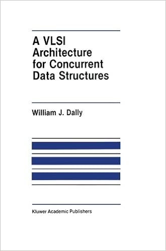
A VLSI Architecture for Concurrent Data Structures by William J. Dally (auth.) PDF
Concurrent information constructions simplify the advance of concurrent courses via encapsulating typical mechanisms for synchronization and commu nication into info buildings. This thesis develops a notation for describing concurrent facts constructions, provides examples of concurrent information constructions, and describes an structure to help concurrent info constructions.
- Mastering VMware Infrastructure 3
- Memory systems and pipelined processors
- Turbo Decoder Architecture for Beyond-4G Applications
- High-speed Analog-to-Digital Conversion
- B2B Integration: Concepts and Architecture
Additional resources for Digital VLSI Design with Verilog: A Textbook from Silicon Valley Polytechnic Institute
Example text
VCS can be faster and neater than DC in displaying a schematic, and it can create schematics for unsynthesizable designs. 24 2 Week 1 Class 1 So, use the optional instructions in your DC Synthesizer Lab 1 Summary sheet to invoke VCS and create a schematic of the source verilog for the Intro_Top design: . Fig. 2-11: The new VCS can create a schematic showing the contents of Intro_Top. The TestBench level of the design can be displayed, but more interesting is the Intro_Top schematic, which, as seen above, shows the three submodules and the inverter on the Z output.
Begin HighByte = LowByte1; Bit = LowByte2[7]; LowByte2[3:0] = LowByte2[7:4]; end All the always assignments above are procedural, because a reg must be assigned procedurally. Notice the difference between verilog and C language declarations: The index range in verilog appears after the type name (reg or wire), not after the name being declared: Verilog C or C++ reg[7:0] HighByte, LowByte; char HighByte[8], LowByte[8]; In verilog, "register" means "regular line-up". Registered data is the defining characteristic of Register-Transfer Logic (RTL), the level of abstraction most frequently used in digital simulation and synthesis.
For example, here is a simple module which ands two inputs with an output delay of one time unit: module And2 (output Z, input A, B); assign #1 Z = A & B; endmodule The assign vector, introducing a continuous assignment, is explained below. Initial Blocks. Our TestBench module contained an initial block. An initial block includes one or more procedural statements which are read and executed by the simulator, beginning just before simulation time 0. An initial block is executed just once during simulation.
Digital VLSI Design with Verilog: A Textbook from Silicon Valley Polytechnic Institute by John Michael Williams
by Edward
4.3


